The F&G study is carried out to help in decision making process for locating the number of Gas and flame detectors.
The goal in design and operation of refineries, storage and handling plants is a plant free of gas releases and fires, the risk of a release or fire is never zero. Some areas of the plant have a greater risk than others. The risk is influenced by the material contained, the conditions under which it is contained, and the equipment and procedures used to contain it.
The risk from flammable or toxic gas releases or fires can be reduced by early detection and subsequent mitigating actions. Detection and response to a release or fire, is often effectively provided by the process operators, in conjunction with their daily activities. However, sometimes the nature of the event is such that a more rapid detection and response is required than can be expected from the operator. Additionally, the increased use of remote monitoring and automation can reduce the time operators spend on the unit, possibly increasing the time to detect a leak. When more rapid detection is necessary than can be provided by the process operator, an instrumented monitoring system can be used.
The fire and gas detection systems are provided on installations for prior identification of the risk from the accidental toxic and flammable gas releases or ignition sources which can constitute a possible threat to the installation or personnel.
Toxic gas, flammable gas, and fire detectors can reduce the risk of a release by reducing the severity. Severity is reduced because faster response is possible. The response may be carried out by the operator or through an automated response. Automated responses include stopping and/or isolating equipment and automated foam, water spray, or deluge systems.
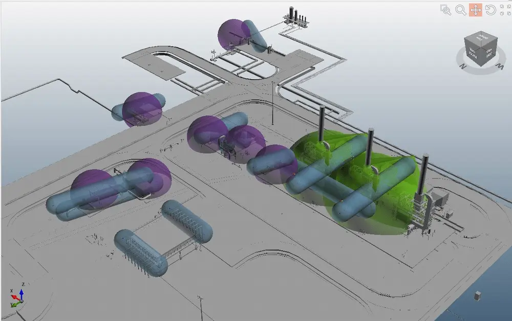
A hybrid approach has been followed for detect 3D modelling i.e. detectors were placed both on scenario based and geographic based approach .The advantage of this approach is that no of detectors required will be comparatively less with the better coverage results. The detectors were placed near LOC scenarios of the equipment and the no. of detectors is minimized based on the geographic location i.e. for nearby equipment common detectors were placed without comprising performance coverage target of the desired equipment’s.
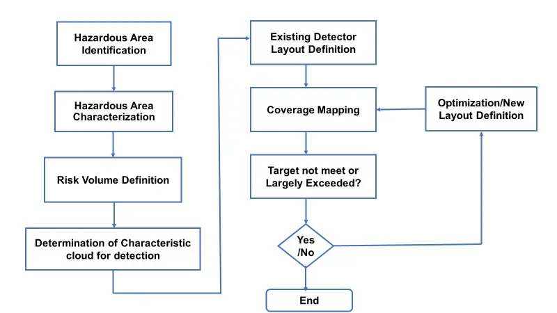
FIRE & GAS MAPPING STUDY METHODOLOGY
Step 1: Hazardous Area Identification
The facility area will be critically assessed for identifying all hazardous areas that are present in the location into different hazardous zones.
Step 2: Hazardous Area Characterization
From the above identification, major accident hazards will be characterized based on the likelihood and frequency of the incident and based on the properties and quantity released.
Step 3: Risk Volume Definition
A representative leak size will be selected based on the standards for all the loss of containment scenarios isolated in step-2.
Step 4: Determination of characteristic cloud for detection
The identified scenarios will be modelled using software to calculate the impact distance in downwind and crosswind direction at prevalent wind conditions at the location.
Step 5: Existing Detector Layout Definition
The existing fire and gas detectors if available in the site will be checked for the maximum distance coverage using the software.
Step 6: Coverage Mapping / Detect 3D Modelling
The drawing file will be imported to the software. Existing detector and impact distance calculated will be overlaid on the 3D map to check if the existing detectors are at adequate location to sense and detect the likely fire and gas dispersion at that location. If existing detectors are not available new hydrocarbon/toxic detectors will be placed near the loss of containment scenarios.
Step 7: Optimization/Detector Layout Definition
Repeat the above steps for all loss of containment scenarios. Optimize the detector location height or change the place of detector location to match the dispersion coverage of the hydrocarbon /toxic release if the detectors are found inadequate to sense or detect the dispersion.
The methodology used for the study have been indicated pictorially.
F&G Study Methodology
The hazardous area of this facility were identified based on the properties of the materials handled and the potential hazards in the systems which could lead to loss of containment events.
The risk from a flammable or toxic material release is the combination of the probability of a leak occurring and the potential consequences should the leak occur. In determining the probability of a leak, the type of operation, the operating conditions, and the equipment involved are all considered. In determining the consequences, the material contained, the size of the leak, the proximity of the leak to other equipment or the fence line, and speed with which the leak might be detected without instruments are all considerations.
In the identified hazardous areas the potentially hazardous equipment / hazardous scenarios were identified and characterized, based on that either Toxic, Flammable gas or Fire detectors will be placed.
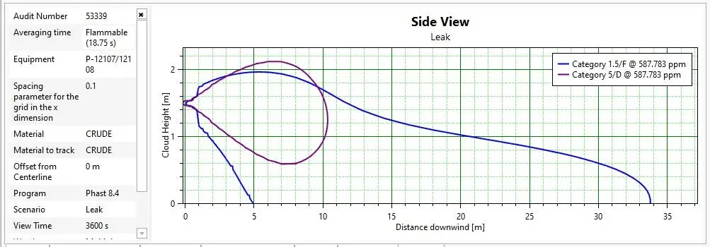
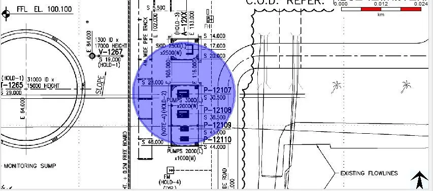
Dispersion modelling of critical scenarios provides the basis for the detector location for minimizing the catastrophe due to release of identified flammable or toxic gas. The expected release of the hydrocarbon/toxic gas during normal or abnormal operations from potential sources due to piping leaks, and dispersion of vapour/gas based on prevalent wind conditions in that location was done through the modelling. Example Dispersion graph and contour is given below.
“Risk Mapping Method” in detect 3D software was used, in line with ISA TR-84.00.07 standard, to assess the detector coverage. Adequate protection using F&GS devices shall be provided to prevent an incident from starting or from escalating.
Combination F&GS devices shall be provided at strategic locations where flammable gases or fires are likely to occur and are likely to increase the area of detectors coverage. This shall include the use of point gas detectors, open path gas detectors for both perimeter and area monitoring of flammable gases, and flame/heat detectors, or a combination thereof, for specific potential leak sources.
There are numerous factors that may affect the number and location of gas detectors. Some of the factors that shall be considered include, but are not limited to, the following:
A. Leak (hole) size, process pressures, and leak rate.
B. Type of facility being protected with gas detectors (onshore, offshore, outdoor, or indoor).
C. Density of equipment, walls, or obstructions in and around the gas detectors.
D. Vapor density of gas in the process.
E. Type of gas hazard being detected (toxic or flammable).
F. Detector technology being installed (point, open path, ultrasound).
Once the type of facility being protected with gas detection equipment, hazardous area, the minimum leak size to be detected, the type of gas hazards and its properties have been determined for locating the detectors then gas detector technology should be considered.
The following are the types of gas detection system considered for the mapping study based on the hazard associated with the facility.